
PROJECTS
Project | 01
Design of Screw Conveyor


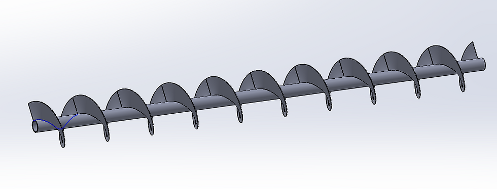


Martin Sprocket & Gear Inc. was investigating a design change in a conveyor system that is used to move silica sand from a recycling operation into a foundry.
This project focuses on designing a screw conveyor that must be cost effective while maintaining efficiency and performance. The newly designed screw conveyor must be 19 feet long and able to transport silica sand at a temperature of 1000 °F at the rate of 400 cubic feet per hour at an incline of 10°. Additionally, it should be able to resist corrosion caused by additives in the sand.
The screw conveyor is designed in three phases namely Conceptual design, Embodiment design and detail design. The conceptual design phase consists of problem definition, gathering information, concept generation and concept selection. Then starts the embodiment design phase where we define product architecture, develop configuration design and parametric design. Later we move to Detail design where we develop final models, drawings and assembly and carry out various analysis.
We started the Conceptual design phase of screw conveyor initially by conducting detailed customer survey. The resulted customer requirements were mapped into engineering characteristics by using House of Quality which further helped us in generating 3 new redesign concepts. These new redesigned concepts were further analyzed, and final concept was selected with the aid of systematic approaches namely morphological chart and weighted decision matrix thus ending the conceptual design phase.
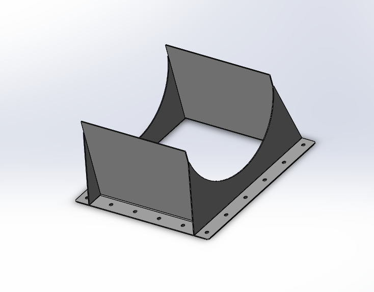
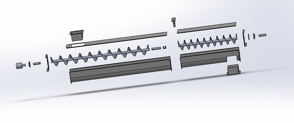
After the completion of conceptual design, we then moved on to embodiment design phase wherein the product architecture was defined by initially conducting physical and functional decomposition of the selected concept. After the product architecture was defined we carried out material selection process for each component separately where in firstly the known factors were established which further helped us in selecting the proper material by using Ashby chart. Later, various manufacturing process was then selected based on the material selected by using PRIMA chart and the final Manufacturing process for each component was selected with the help of weighted decision matrix. Some of the standardized components like motor, coupling shaft, bolts, etc. were directly purchased. DFM and DFA guidelines were also followed to produce a cost-effective design where in DFM and DFA analysis sheets were created. Lastly, tolerance analysis for the key components was conducted thus concluding the embodiment design phase.
In Detail design phase, reliability analysis, cost analysis, ergonomics and safety analysis of each component was carried out. Failure Mode and Effect Analysis (FMEA) of critical components was also carried out wherein the corrective actions for each failure was also recommended. Finally, 3D CAD models and 2D CAD drawings of each component and final assembly of the system was created by taking tolerance into account.
Project | 02
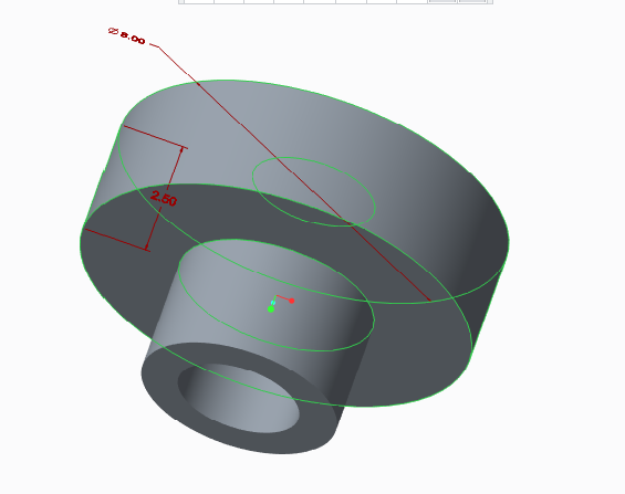
Manufacturing of Hydraulic Manifold block by Additive Manufacturing


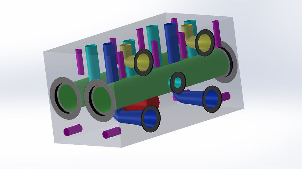


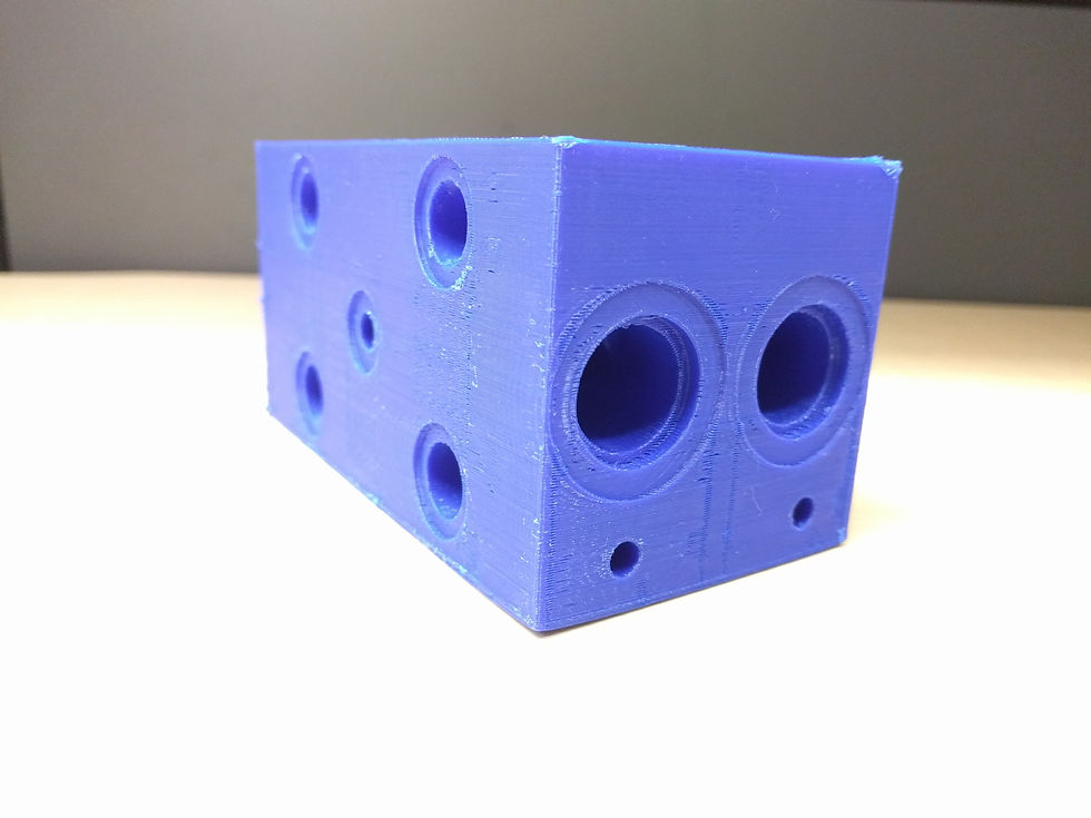
Hydraulic Manifold Block is a component that regulates fluid flow between pump actuators and other types of hydraulic circuit. It could be compared to a switchboard in an electrical circuit because it lets the operator control the amount of fluid flow between the components of hydraulic machinery.
The current process of manufacturing Hydraulic Manifold Block involves various steps of processes starting with CAD Design, followed by manufacturing processes namely casting, milling and marking, drilling, honing, cleaning and deburring respectively. This conventional manufacturing process is very time consuming and results in abrupt angled junctions between flow parts which can cause flow separation and stagnation. We chose to manufacture this Hydraulic Manifold Block using Direct Metal Laser Sintering (DMLS) method of Additive Manufacturing and compared various parameters like time consumption, cost effectiveness, design complexity limits, flow path optimization, product efficiency etc. with those of conventional method.
Since Additive Manufacturing is popularly known as “complexity free” manufacturing, it’s use in near future will increase to produce optimized shapes and structures.
The project aims to:
1. Optimize the design of Hydraulic Manifold Block for significant weight reduction and material saving.
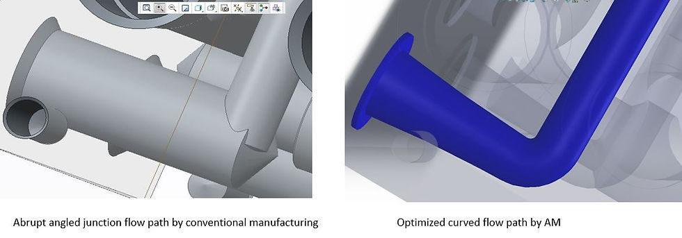
2. Optimize the block’s internal flow channels for obtaining geometrically complexed flow paths, smoother fluid flow at angular sections and eliminating material erosion at sharp corners, hereby justifying the geometric complexity design benefits of Additive Manufacturing.
3. Justification of use of Direct Metal Laser Sintering (DLMS) system over conventional method of mass production based on parameters such as design complexity, accuracy, production time, production cost, product efficiency, flow performance, product life cycle and verity in material of construction.
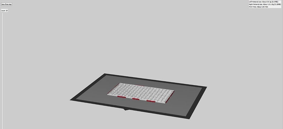
We concluded that production of Manifold Block by Additive manufacturing can lead to significant reduction in build time. Also, redesign and optimization of part consisting only of channels along with some secondary supports in replacement of the solid block can lead to about 60% of weight reduction and material saving. Moreover, optimization of abrupt angled junctions to curved flow paths which is only possible by Additive Manufacturing resulted in optimized flow properties of the fluid.
While building our part on Flash-forge 3D printer for the first time, the nozzle containing build material was blocked. We tried printing our part again after cleaning the nozzle but it blocked again. After careful study, it came to our knowledge that as the material was wet and deteriorated, thus we replaced it with new material and our build was successful.
Project | 03
Prototype of Tube Bending Machine


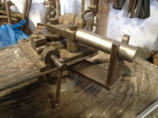


Today, tubing is used is in many different shapes and forms due to the advancement in pipe and tube bending machines. Tubing can be found in just about anything in our lives from dishwashers, cars, airplanes, trains, water lines and so much more. Pipe bending is basically a metal forming process to permanently form pipes and tubes in a specific way. There are different types of tube bending including form-bound and free form bending, along with heat supported and cold forming processes.
Our present state of technology allows the production of complex construction elements rationally and precisely in one single working step by forming under bending conditions. But particularly in pipeline construction or in the installation business, where bending as a production method has been neglected for a long time and conventional - often expensive - connection techniques (e.g. welding) were used instead, bending has gained importance in the past years, due to its large variety of advantages.
This is because the modern tube bending machines have made it possible to optimally combine processing precision with productivity, not forgetting the high operation comfort.
In comparison with welding, the bending technology shows up with several economical as well as production-technological advantages.
For example, by saving expensive fittings, not only material costs,but also the expenses for acquisition and storage can be lowered Immensely.
Production time and costs for bending are also clearly lower than those for welding connections (including preparation of the welding seam and finishing works). Production failures, which often occur when welding, are completely avoided with the application of the bending method. Furthermore, due to lower pipeline resistance, the fluidic behaviour is improved in bent tubes, compared to conventional fittings.
By eliminating connection parts, which always represent critical construction elements, potential danger zones in the pipeline system are reduced to a minimum, which finally results in a longer service life of the pipeline system.Very large bending forces can be generated with minimal human effort.
The only human effort required is loading of the tubing and switching on the hydraulic motor. This minimalises accidents and results in a safe and damage free operation